Gcalo
New member
360 430 Front Shock Removal
Front shock removal is quite simple but if done from a lift it may be even easier.
I do caution not to support the car on jack stands, because you have to tug a bit with the nut securing the front torsion bar to the lower shock bolt. I supported my car on 5 short pieces of a 2”X10” on each side about 6” behind each wheel. This gives full support with no car movement.
You will need a 10 mm, 17 mm, and 19 mm socket as well as a 17 mm and 19 mm flat open end wrenches. If you have also a 17 mm open end wrench about 4” (100 +/- mm) in length it makes the torsion bar nut removal easier after the two nuts are loosened.
The nut on the tie rod end of the torsion bar has only one set of 17 mm cutouts. So a short 17 mm open end makes movement in there quite easy.
Remove the upper 10 mm bolt that holds the shock electrical connector, and then remove the connector.
I digress from the W/S manual procedure to remove the coilover. I suggest to put a 19 mm socket on the lower shock nut and a 19 mm open end on the nut up against the torsion tie rod end side of this assembly. Loosen that 19 mm nut just a bit so you can move the 19 mm open end wrench a bit. Move the 19 mm open end so that you can locate the 17 mm cutouts on the tie rod not to install the 17 mm regular length open end. I braced the 19 mm wrench and then taped against the 17 mm to just break the bond.
I then put my floor jack under the brake rotor with a hockey puck between them and put just a slight bit of upward pressure on the assembly. It makes removing the swat bar tie rod thread assembly much, much easier. The W/S manual says nothing of this. I then put the shorter 17 mm open end on the tie rod nut and worked it so I could free it completely and rotated it slightly upward out of the way.
I then used the 17 mm socket and with the hammer lightly taped each of the two upper shock mount bolts to slightly loosen them. I then removed both of the upper shock mount bolts.
Next use the 19 mm socket on the shock bottom bolt nut and while holding the 19 mm open end on the other side completely removed the securing nut and washer. While supporting the shock assembly slightly with one hand I gradually taped the lower shock bolt until it came free out the other side. I then removed the floor jack and moved out of the way.
The shock assembly will easily remove over the wishbone but be careful as you lift it out, because if you are too energetic you can ding the inside of the fender leaving a noticeable dent on the outside. (No, I did not ding my car.).
Another word of caution, use some type of a permanent marker and mark on the top of the casting which is Right and which is Left. Inspect the lower rubber bushings for wear and integrity and replace if necessary. They are P/N 157630. They must be press fit.
Replacement is the reverse. Don’t forget to use the floor jack to put slight upward pressure on the rotor to make re-installation of the tie rod threads and installation of the two upper bolts easy.
Torque values: upper shock bolts – 36.88 ft-lbs (50Nm); lower shock bolt nut – 44.25 ft-lbs (60 Nm)
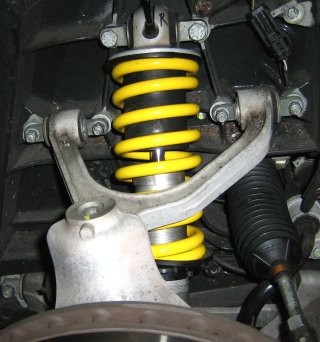
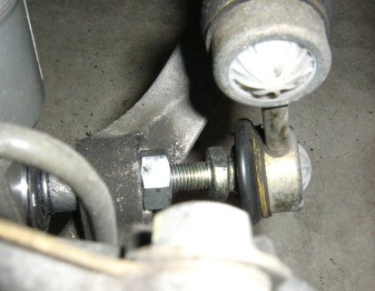
Photo below of shock installed and then the sway bar tie rod assembly almost fully removed.