Gcalo
New member
I am trying this again and hope the photos properly align.
I have not done this process as I do not own a 355 but a friend who did is extremely competent.
It should all make sense.
There are several problems that can occur with the actuator that will trigger a suspension light. The actuator is dealt with only here, there may be other problems which are beyond the scope of this article.
__________________________________________________
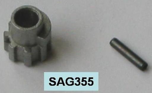
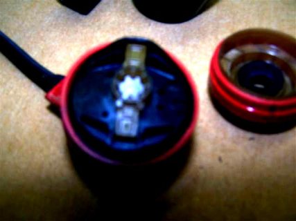
1) The small gear on the top of the shock shaft is broken. This can be repaired with a replacement from various parts sources. The procedure is here.
View attachment 82092
Instructions:
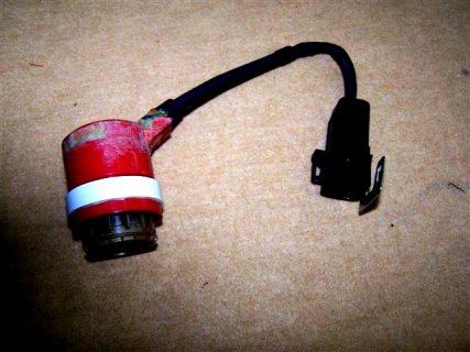
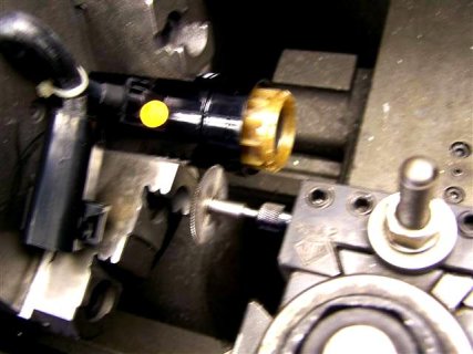
Under the engine cover there are two round red shock actuators, one on each side of the bay. They are showing through cutouts in a shroud. The first step is to remove the shrouds, which are attached by two hex bolts, one at the rear, and one at the middle (there may be a third at the front, but mine were not installed.) Once those bolts are off, release the actuator control wire from the white plastic guide, and the shroud should come out pretty easy, though they are kind of wedged under the lip.
Once the shroud is off, I would first check each actuator to see if it is working. (You need someone to start the car to do this while you are looking at the actuator.) First, remove the actuator by pulling back the locking clip that is at the base. Note how it goes back in, seating in the two grooves on the sides of the actuator. Once it is off, you can remove the red actuator body by pulling straight up. If there is not enough slack in the wire, you have to unscrew the retaining clip that mounts to the side of the bay. With the actuator off, have someone start the car, and watch the interior gear. if it spins, just as the car starts, it is working. Now, examine the small chrome-colored gear sticking up out of the top of the shock. See if it has any teeth missing, or is cracked or deformed. If it is, that's your culprit. If it is not, you can check the other one now. Same procedure.
If the gear is broken, you need to order one from a parts source. They are about $30, and readily available.
To replace the gear:
First, you must remove the tiny locking pin that is seated in the small hole on the side of the gear. This requires a small wire nail or driver. REALLY small. Simply tap the pin out with a small hammer and a wire brad. DO NOT LOSE the pin. Put a piece of white tape on the other side to catch it just in case. Some replacement pins are too long, and can be a couple thousandths longer than the OEM. Once the
pin is out, the gear will pop right off.
Now, get a 2" or so long needle -- a sewing needle--- or a tailor's needle is better - one with the pearl or plastic ball on one end so it won't just fall through the hole.
Line up the holes in the replacement gear with the hole in the shock shaft. Use a small flashlight behind the hole to make it easy to see when they were lined up exactly. Pass the needle through the hole. Now, take the old locking pin and slide it onto the shaft of the needle.
Slide it down until it lines up with the holes. You may be able to get it seated by hand. You may have to retract the needle a bit then tap the pin with a small hammer to get it started in the hole. Once it was in enough to hold itself, use a pliers with flat jaws to squeeze the pin in the rest of the way -- using the back of the gear for puchase and slowly work it in. If you can get enough room to use the hammer, you could probably just tap it in, though an off center strike could send the pin flying. WARNING - getting the pin in can be pretty frustrating. If you drop the pin, I suggest having a magnet probe handy to find it on the floor -- it's really tiny.
Once the gear is on and the pin in place, put the actuator cap back on, replace the locking clip. Give a gentle tug to make sure it's locked in. remount the wires. If you're feeling lucky, replace the shroud (or do it after you're sure the problem is solved!) Now, start the car. The light will still be on. Take a drive for a 1/4 mile drive or so and cycle the sport/comfort setting a couple of times (light stayed on). Turned it off. Restarted, and the light stayed OFF. The system rotates each actuator independently when the car is started, so it takes a couple cycles to get them synced.
__________________________________________________ __
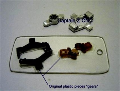
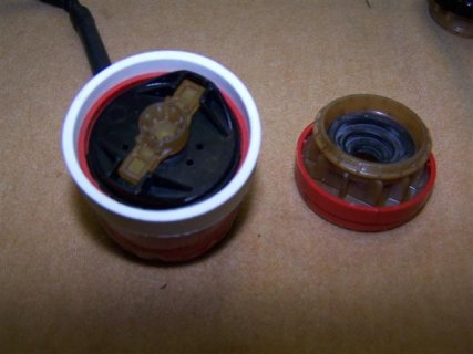
2) The plastic drive parts (not the black plastic gears under them) are broken.
Take the actuator off and remove the rubber gasket on the bottom. You can look inside and see if the brown and black plastic drive parts are broken, (not easy, but doable). This can be repaired by Captain Z or parts are available separately so you can DIY.
View attachment 82093
http://captainzcnc.com/_wsn/page3.html
__________________________________________________ _________________________________________________
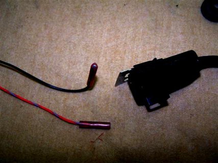
3) The motor is not working.
View attachment 82094
View attachment 82095
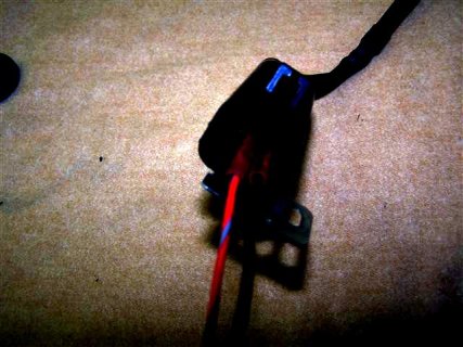
To test this hold the actuator in your hand while a helper cycles the ignition on and off, or you can make test connectors by cutting the insulation off just at the end on the metal ferrule of a red butt connector and crimping a lead on the other end. These will fit on the male terminals in the actuator connector and allow bench testing.
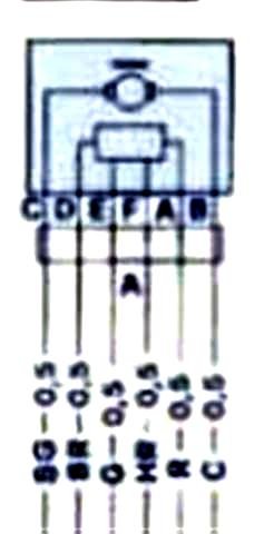
You should feel some movement of the motor before it stops due to gears jamming. If there is no movement check the plug for 12 volts with key on. See schematic here
attached below.
C (brown) = 12 volt positive or negative depending on rotation.
B (blue) = 12 volt positive or negative depending on rotation.
Probe C (brown) and B (blue) wires for 12 volts/ground (depending on direction of rotation) with key on to prove power supply to actuator.
If there is continuity to the motor and you feel no movement with the key on then there may be a broken wire. This is a DIY repair; you must open the top half, not an easy task, but it can be done.
The '89-'91 model Vettes used one flavor of that shock actuator, while the '92-'95 models used the same unit but with a different "stop" for the motor (fx3 suspension option on all versions).
You can have them rebuilt for $125 here: http://captainzcnc.com/index.html
The Corvette Delco part number is 22114337.
You can get them new here, as well as the clips and various small parts for them: http://www.dougrippie.com/drm/suspen...ardware FX-3
If you play around with them you'll be able to find what you need or make one from another car work perfectly on your 355.
If there is continuity (12 volt power) and no broken wires the motor section has simply failed internally, in which case there is no recourse I can think of but to buy another actuator. The Corvette motor will not work as it has only one Hall Effect sensor
Pin Labels and wire colors of connector on actuator, not the connector from the car harness
View attachment 82096
As you hold it in your hand looking at the open end with the latch on top
From upper left, D (black), F (yellow), E (green),
From lower left, A (red), B (blue), C (brown)
View attachment 82097
Examples:
C (brown) on actuator connector = pink/yellow in car harness connector.
B (blue) on actuator connector = orange in car harness connector.
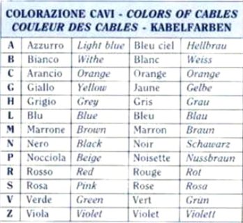
Use this chart to correspond colors on car harness connector
View attachment 82098
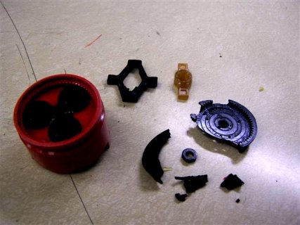
4) The plastic gears (probably the larger plastic ring gear) in the lower half of the actuator are broken.
View attachment 82099
This can be repaired by obtaining a new Corvette actuator, separating the gear section from the motor section on both actuators and replacing the broken gears with the new gears from the Corvette lower section. The procedure is outlined below.
You do exactly the same procedure to both the Ferrari actuator and the Corvette actuator.
The first step is to carefully separate the motor section from the gear train section.
I used a lathe and a Dremel tool with flex shaft fixed to the tool post with a fine tooth cut-off saw blade in the collet.
I tied the pigtail up so it wouldn’t flail about when I chucked up the actuator in the lathe with the gear section facing outwards. The lathe is set on slowest RPM, or you could turn the chuck manually while advancing the cut-off blade with the cross feed.
Then I cut exactly in the center of the recessed section, you must be very careful to cut only the depth of the red/black plastic, (about .070) and not into the underlying brown plastic, which both locates and determines the depth of the gear case.
View attachment 82105
You must also be careful not to let the parts separate until you are ready to separate them.
Once cut the proper depth, remove the actuator from the lathe and hold with the gear section down and carefully lift off the motor section.
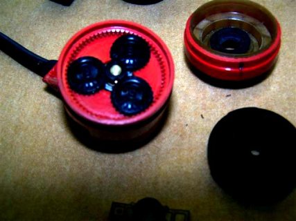
The three black plastic gears will probably stick in the motor section; note their position (equidistant radially) so you can replace them in the gear section correctly. Note orientation of small black plastic spacer.
View attachment 82100
Once both actuators have been sectioned, and gears have been replaced, lightly coat the area the joining ring will cover with Devcon Plastic Welder, and join the two sections together, making sure that all the new parts from the Corvette actuator are correctly located in the Ferrari gear section and that no epoxy can get inside the gear section, and that the rubber gasket is in place, then let set for 4 hours.
View attachment 82101
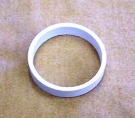
I made the joining ring by turning down a 1 ½ plastic pipe plug. That was all I could find with the necessary ID and OD. You should be able to get two rings out of one plug.
View attachment 82102
OD = 1.750
ID = 1.550
Length = 0.350
View attachment 82103
The finished product, it would have looked nicer had I not ripped the motor section apart, but I wanted to see what was there and this one will go on the front where you can’t see it.
This procedure has been tested and it works.
I have not done this process as I do not own a 355 but a friend who did is extremely competent.
It should all make sense.
Shock Actuators
There are several problems that can occur with the actuator that will trigger a suspension light. The actuator is dealt with only here, there may be other problems which are beyond the scope of this article.
__________________________________________________
1) The small gear on the top of the shock shaft is broken. This can be repaired with a replacement from various parts sources. The procedure is here.
View attachment 82092
Instructions:
Under the engine cover there are two round red shock actuators, one on each side of the bay. They are showing through cutouts in a shroud. The first step is to remove the shrouds, which are attached by two hex bolts, one at the rear, and one at the middle (there may be a third at the front, but mine were not installed.) Once those bolts are off, release the actuator control wire from the white plastic guide, and the shroud should come out pretty easy, though they are kind of wedged under the lip.
Once the shroud is off, I would first check each actuator to see if it is working. (You need someone to start the car to do this while you are looking at the actuator.) First, remove the actuator by pulling back the locking clip that is at the base. Note how it goes back in, seating in the two grooves on the sides of the actuator. Once it is off, you can remove the red actuator body by pulling straight up. If there is not enough slack in the wire, you have to unscrew the retaining clip that mounts to the side of the bay. With the actuator off, have someone start the car, and watch the interior gear. if it spins, just as the car starts, it is working. Now, examine the small chrome-colored gear sticking up out of the top of the shock. See if it has any teeth missing, or is cracked or deformed. If it is, that's your culprit. If it is not, you can check the other one now. Same procedure.
If the gear is broken, you need to order one from a parts source. They are about $30, and readily available.
To replace the gear:
First, you must remove the tiny locking pin that is seated in the small hole on the side of the gear. This requires a small wire nail or driver. REALLY small. Simply tap the pin out with a small hammer and a wire brad. DO NOT LOSE the pin. Put a piece of white tape on the other side to catch it just in case. Some replacement pins are too long, and can be a couple thousandths longer than the OEM. Once the
pin is out, the gear will pop right off.
Now, get a 2" or so long needle -- a sewing needle--- or a tailor's needle is better - one with the pearl or plastic ball on one end so it won't just fall through the hole.
Line up the holes in the replacement gear with the hole in the shock shaft. Use a small flashlight behind the hole to make it easy to see when they were lined up exactly. Pass the needle through the hole. Now, take the old locking pin and slide it onto the shaft of the needle.
Slide it down until it lines up with the holes. You may be able to get it seated by hand. You may have to retract the needle a bit then tap the pin with a small hammer to get it started in the hole. Once it was in enough to hold itself, use a pliers with flat jaws to squeeze the pin in the rest of the way -- using the back of the gear for puchase and slowly work it in. If you can get enough room to use the hammer, you could probably just tap it in, though an off center strike could send the pin flying. WARNING - getting the pin in can be pretty frustrating. If you drop the pin, I suggest having a magnet probe handy to find it on the floor -- it's really tiny.
Once the gear is on and the pin in place, put the actuator cap back on, replace the locking clip. Give a gentle tug to make sure it's locked in. remount the wires. If you're feeling lucky, replace the shroud (or do it after you're sure the problem is solved!) Now, start the car. The light will still be on. Take a drive for a 1/4 mile drive or so and cycle the sport/comfort setting a couple of times (light stayed on). Turned it off. Restarted, and the light stayed OFF. The system rotates each actuator independently when the car is started, so it takes a couple cycles to get them synced.
__________________________________________________ __
2) The plastic drive parts (not the black plastic gears under them) are broken.
Take the actuator off and remove the rubber gasket on the bottom. You can look inside and see if the brown and black plastic drive parts are broken, (not easy, but doable). This can be repaired by Captain Z or parts are available separately so you can DIY.
View attachment 82093
http://captainzcnc.com/_wsn/page3.html
__________________________________________________ _________________________________________________
3) The motor is not working.
View attachment 82094
View attachment 82095
To test this hold the actuator in your hand while a helper cycles the ignition on and off, or you can make test connectors by cutting the insulation off just at the end on the metal ferrule of a red butt connector and crimping a lead on the other end. These will fit on the male terminals in the actuator connector and allow bench testing.
You should feel some movement of the motor before it stops due to gears jamming. If there is no movement check the plug for 12 volts with key on. See schematic here
attached below.
C (brown) = 12 volt positive or negative depending on rotation.
B (blue) = 12 volt positive or negative depending on rotation.
Probe C (brown) and B (blue) wires for 12 volts/ground (depending on direction of rotation) with key on to prove power supply to actuator.
If there is continuity to the motor and you feel no movement with the key on then there may be a broken wire. This is a DIY repair; you must open the top half, not an easy task, but it can be done.
The '89-'91 model Vettes used one flavor of that shock actuator, while the '92-'95 models used the same unit but with a different "stop" for the motor (fx3 suspension option on all versions).
You can have them rebuilt for $125 here: http://captainzcnc.com/index.html
The Corvette Delco part number is 22114337.
You can get them new here, as well as the clips and various small parts for them: http://www.dougrippie.com/drm/suspen...ardware FX-3
If you play around with them you'll be able to find what you need or make one from another car work perfectly on your 355.
If there is continuity (12 volt power) and no broken wires the motor section has simply failed internally, in which case there is no recourse I can think of but to buy another actuator. The Corvette motor will not work as it has only one Hall Effect sensor
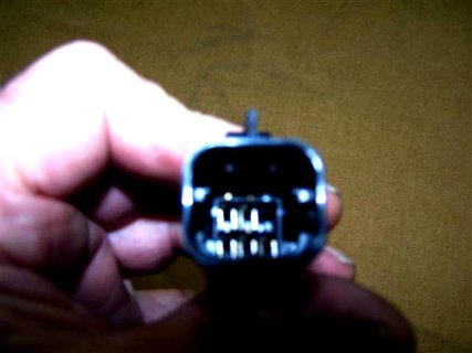
Pin Labels and wire colors of connector on actuator, not the connector from the car harness
View attachment 82096
As you hold it in your hand looking at the open end with the latch on top
From upper left, D (black), F (yellow), E (green),
From lower left, A (red), B (blue), C (brown)
View attachment 82097
Examples:
C (brown) on actuator connector = pink/yellow in car harness connector.
B (blue) on actuator connector = orange in car harness connector.
Use this chart to correspond colors on car harness connector
View attachment 82098
4) The plastic gears (probably the larger plastic ring gear) in the lower half of the actuator are broken.
View attachment 82099
This can be repaired by obtaining a new Corvette actuator, separating the gear section from the motor section on both actuators and replacing the broken gears with the new gears from the Corvette lower section. The procedure is outlined below.
You do exactly the same procedure to both the Ferrari actuator and the Corvette actuator.
The first step is to carefully separate the motor section from the gear train section.
I used a lathe and a Dremel tool with flex shaft fixed to the tool post with a fine tooth cut-off saw blade in the collet.
I tied the pigtail up so it wouldn’t flail about when I chucked up the actuator in the lathe with the gear section facing outwards. The lathe is set on slowest RPM, or you could turn the chuck manually while advancing the cut-off blade with the cross feed.
Then I cut exactly in the center of the recessed section, you must be very careful to cut only the depth of the red/black plastic, (about .070) and not into the underlying brown plastic, which both locates and determines the depth of the gear case.
View attachment 82105
You must also be careful not to let the parts separate until you are ready to separate them.
Once cut the proper depth, remove the actuator from the lathe and hold with the gear section down and carefully lift off the motor section.
The three black plastic gears will probably stick in the motor section; note their position (equidistant radially) so you can replace them in the gear section correctly. Note orientation of small black plastic spacer.
View attachment 82100
Once both actuators have been sectioned, and gears have been replaced, lightly coat the area the joining ring will cover with Devcon Plastic Welder, and join the two sections together, making sure that all the new parts from the Corvette actuator are correctly located in the Ferrari gear section and that no epoxy can get inside the gear section, and that the rubber gasket is in place, then let set for 4 hours.
View attachment 82101
I made the joining ring by turning down a 1 ½ plastic pipe plug. That was all I could find with the necessary ID and OD. You should be able to get two rings out of one plug.
View attachment 82102
OD = 1.750
ID = 1.550
Length = 0.350
View attachment 82103
The finished product, it would have looked nicer had I not ripped the motor section apart, but I wanted to see what was there and this one will go on the front where you can’t see it.
This procedure has been tested and it works.
Attachments
-
 shock1.jpg13.1 KB · Views: 3,557
 -
 shock2.jpg36.9 KB · Views: 3,249
 -
 shock3.JPG44.6 KB · Views: 3,110
 -
 shock4.JPG48.9 KB · Views: 3,112
 -
 shock5.jpg13.9 KB · Views: 3,107
 -
 shock6.JPG27.8 KB · Views: 3,136
 -
 shock7.jpg53.9 KB · Views: 3,159
 -
 shock8.JPG43.9 KB · Views: 3,086
 -
 shock10.JPG43.6 KB · Views: 3,067
 -
 shock11.JPG28.8 KB · Views: 3,112
 -
 shock12.JPG37.8 KB · Views: 3,083
 -
 shock13.JPG13.8 KB · Views: 3,134
 -
 shock14.JPG51.3 KB · Views: 3,184
 -
 shock9.JPG43.9 KB · Views: 3,085