What's new
Club Scuderia

This is a sample guest message. Register a free account today to become a member! Once signed in, you'll be able to participate on this site by adding your own topics and posts, as well as connect with other members through your own private inbox!

  • Please take a minute to read this thread about our recent server issues and forum platform Switch

355 Door Removal and Refurbishment

Terry

Active member
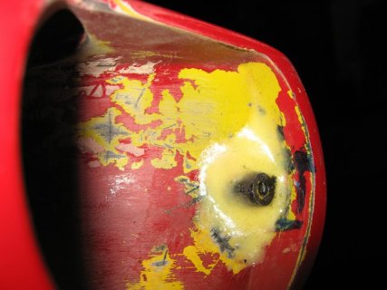
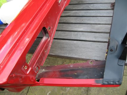
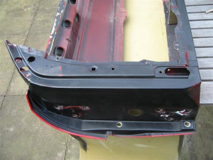
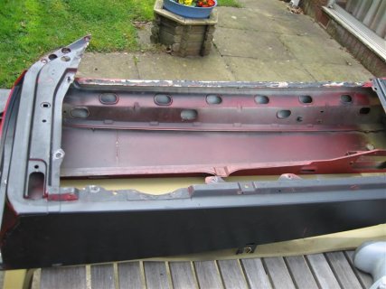
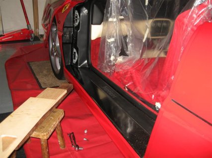
Over the last month or so I have removed both doors for a refurbishment - new paint and seals etc plus repainting the forward area of the door frame, an area not easy to access with the door on. This may be of interest to anyone else wishing to remove their doors.

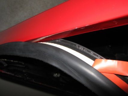
A little masking tape along the rear edge of the wing may help avoid marks if any rub occurs during removal.

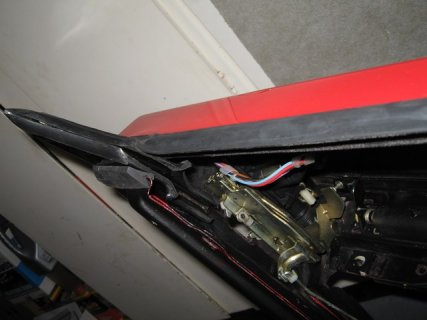
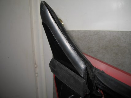
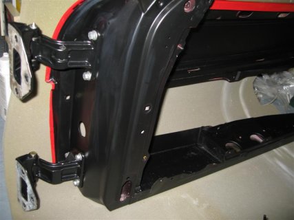
First remove the door hold open bolt on the hinge and fully retract the rod otherwise it will hang up on the hinge when removing the door.
IMG_6176 (Medium).JPG

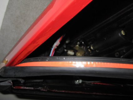
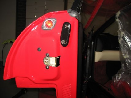
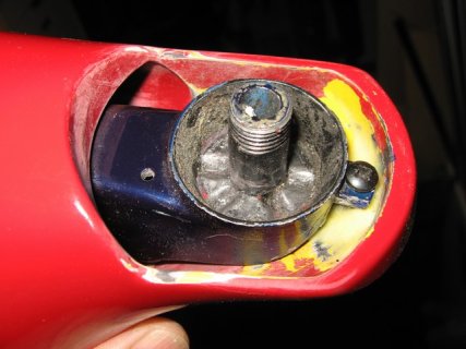
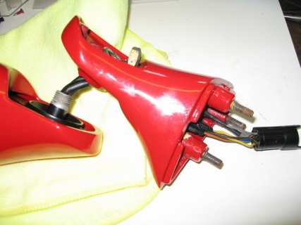
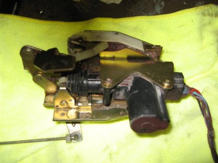
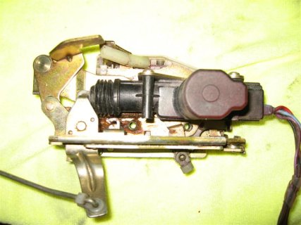
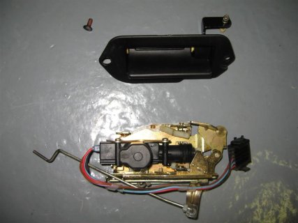
The electrical plug is a quick release connector which hinges off at the bottom of the plug
IMG_6178 (Medium).JPG

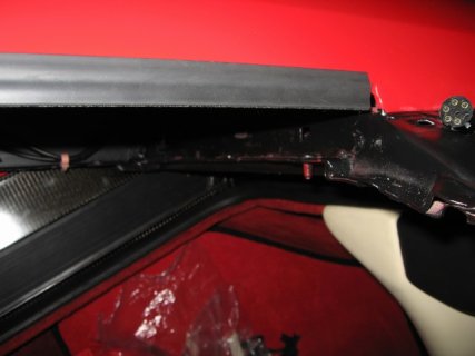
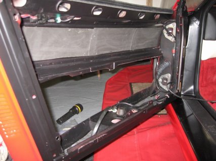
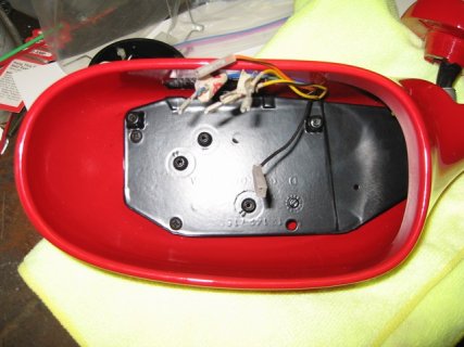
Support the door (it is heavy with all the glas, mechanism and trim) and remove all six 8mm hinge bolts.
IMG_6179 (Medium).JPG

Lift the door clear and place in a safe place.
IMG_6181 (Medium).JPG

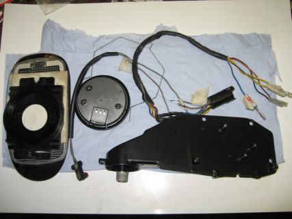
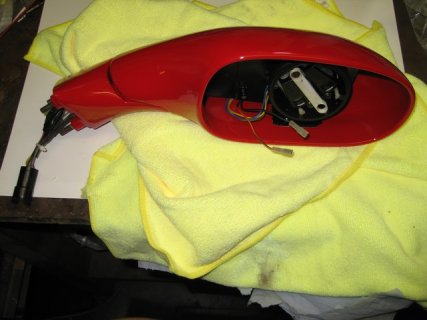
The door trim, glass and glass mechanism could be removed before removing the door to make handling easier.
 
The pictures will be between both doors for illustration.

Door removed. Hold open rod connects to the top hinge and interior light switch uses bottom hinge.
IMG_6048 (Medium).JPG

Door trim off via a few screws along the rear and bottom edge plus the armrest and pull handle.
IMG_6061 (Medium).JPG
 
Next the glass frame can be removed. You need to disconnect the internal door open handle and the window motor cable before moving away.

IMG_6074 (Medium).JPG

I removed the glass then removed the connector from the motor instead of breaking the connection at the bottom of the door.

IMG_6076 (Medium).JPG

The glass is secured with two 6mm bolts either end at the bottom of the glass.
 
Remove the forward glass guide.

IMG_6083 (Medium).JPG

The rear lock mechanism is easily removed via 3 6mm screws in the rear of the door.

IMG_6104 (Medium).JPG

A close up of the connection for the key operated lock

IMG_6105 (Medium).JPG

Lock mechanism removed.

IMG_6108 (Medium).JPG
 
Take an easy chair and clean then relube the lock mechanism.

The motor is for the central locking and easy to replace if faulty.
 

Attachments

  • IMG_6115 (Medium).JPG
    IMG_6115 (Medium).JPG
    63.1 KB · Views: 788
  • IMG_6116 (Medium).JPG
    IMG_6116 (Medium).JPG
    64.6 KB · Views: 782
Door stripped and ready for off to the paint shop.
 

Attachments

  • IMG_6121 (Medium).JPG
    IMG_6121 (Medium).JPG
    69.7 KB · Views: 797
  • IMG_6125 (Medium).JPG
    IMG_6125 (Medium).JPG
    62.6 KB · Views: 801
  • IMG_6126 (Medium).JPG
    IMG_6126 (Medium).JPG
    65.3 KB · Views: 793
  • IMG_6128 (Medium).JPG
    IMG_6128 (Medium).JPG
    73.8 KB · Views: 788
Other parts were then sent for powder coating.

All hinges

IMG_6254 (Medium).JPG

Interior mirror attachment covers and rear window support. Also sent the rear view mirror inner support bracket.

IMG_6256 (Medium).JPG

Outer support frames for mirrors and forward glass.

IMG_6259 (Medium).JPG
 
Door back from painting and masked ready for a coat of satin black to the interior.

IMG_6367 (Medium).JPG

Interior painted.

IMG_6378 (Medium).JPG

Exterior basic polishing prior to fitment of seals etc.

IMG_6379 (Medium).JPG

Hinges back from powder coating, now require new bushes.

IMG_6381 (Medium).JPG
 
I replaced the hinge bushes on the top hinges for both doors due to wear. I also used new hinge pins.

IMG_6382 (Medium).JPG

The old bushes can be tapped out with a drift (hopefully).

I installed the new bushes applying copper slip then pulling home with 8mm bolts. A drift used during installation could easily cause misalignment and/or fracture of the bush so care is needed at this stage.

IMG_6385 (Medium).JPG

IMG_6386 (Medium).JPG

Hinges assembled ready for refit to door. Be sure to fit the top hinge with the hinge pin facing upwards and the bottom hinge with the hinge pin facing down. This will allow the doors to be removed via the pin removal rather than the entire hinge.

IMG_6391 (Medium).JPG

Reassemble hinges to door with new hardware.

IMG_6392 (Medium).JPG
 

Attachments

  • IMG_6387 (Medium).JPG
    IMG_6387 (Medium).JPG
    41.5 KB · Views: 759
  • IMG_6393 (Medium).JPG
    IMG_6393 (Medium).JPG
    54.1 KB · Views: 761
Key lock clean

The key locks were looking scuffed and a little tatty.

IMG_6457 (Medium).JPG

The locks can be easily disassembled by removing a spring clip and circlip

IMG_6459 (Medium).JPG

IMG_6462 (Medium).JPG

Whilst apart the locks can be painted.

IMG_6486 (Medium).JPG

The locks were cleaned, regreased, assembled then ready for refit into the door.

IMG_6493 (Medium).JPG
 
External Handle

The external handle can be disassembled by removing the lock pin at one end. A suitably sized drill works well as a punch.

IMG_6164 (Medium).JPG

The square shaft can be withdrawn to expose all parts

IMG_6165 (Medium).JPG

With the handle apart, a thorough good clean and lube prior to reassembly.

IMG_6170 (Medium).JPG

Ready to refit to door.

IMG_6247 (Medium).JPG

IMG_6249 (Medium).JPG
 
Passenger side frame prepared and ready for door installation.

The stool and wood supports the door at around the correct height for hinge alignment.
 

Attachments

  • IMG_6482 (Medium).JPG
    IMG_6482 (Medium).JPG
    69.6 KB · Views: 403
The lock mechanism refitted together with key lock and external door opening handle. The plastic couplings between the key lock and lock mechanism can be seen in this picture. A few people have reported that these have failed causing no reaction from the door lock key to unlock the door.

IMG_6402 (Medium).JPG

The front hinge retaining plates and with wiring harness installed.

IMG_6403 (Medium).JPG
 
The new windows seals have an adhesive strip pre fitted. The seal is a one piece around the rear window support pillar to the front of the door glass.

View attachment 83017

Hook the seal under the lower edge of the door edge then sqeeze upwards to hook the upper lip over the top edge of the door removing the adhesive cover strip at the same time.

View attachment 83018

The seal will finish a little short of the door mirror support but this is covered after the wing mirror is fitted.

View attachment 83019
 

Attachments

  • IMG_6495.JPG
    IMG_6495.JPG
    38.7 KB · Views: 431
  • IMG_6497.JPG
    IMG_6497.JPG
    41.6 KB · Views: 434
  • IMG_6496.JPG
    IMG_6496.JPG
    36.2 KB · Views: 431

Attachments

  • IMG_6498.JPG
    IMG_6498.JPG
    52.8 KB · Views: 432
  • IMG_6499.JPG
    IMG_6499.JPG
    35.3 KB · Views: 433
  • IMG_6506.JPG
    IMG_6506.JPG
    43.3 KB · Views: 432
  • IMG_6404.JPG
    IMG_6404.JPG
    22.5 KB · Views: 430
Whilst the door was stripped, I fitted some additional insulation to the inner skin of the door and along the bottom inner surface. I used the solid rubbery self adhesive type which is around 3mm thick. Be sure to leave the drain holes open on the bottom of the door.

It may be my imagination but with the insulation the doors have a more solid feel and the bass from the speakers is slightly better.

View attachment 83024
 

Attachments

  • IMG_6505.JPG
    IMG_6505.JPG
    71.1 KB · Views: 434
Door wing mirror

I had previously repaired the LH door rear mirror but the RH side also seemed a little loose at the hinge point so I decided to strip it down for investigation.

One attachment point for the inner support at the hinge point had broken away so I made up a new one from hollow carbon rod and bedded it into some epoxy resin impregnated with carbon fibres.

View attachment 83025

Did a trial fit before sending the mirror housing off to the paint shop with the support frame away for powder coating. Prior to painting I sanded the hinge area to ensure a good fit especially to avoid any chaffing at the hinge point which could later chip the paint.

View attachment 83026

Everything prepared ready for re-assembly.

View attachment 83027

It is necessary to remove the plug from the mirror motor connection in order to feed the wires through the hinge point. The RH mirror has the additional two wires for the sensor which I cut at the door connector then reconnected and covered with heat shrink. A bit of a fiddle getting the wires through in the right orientation.

View attachment 83028

View attachment 83029

The assembly ready to fit the glass. I found that the glass clip can be fully fitted and the glass will then "pop" into place. Be careful to only push in the centre where the glass is supported to avoid you know what.

View attachment 83030

I used a new mirror seal and new foam inside the mirror support.

View attachment 83031

View attachment 83032
 

Attachments

  • IMG_6145.JPG
    IMG_6145.JPG
    64.3 KB · Views: 394
  • IMG_6144.JPG
    IMG_6144.JPG
    67.2 KB · Views: 405
  • IMG_6435.JPG
    IMG_6435.JPG
    60.7 KB · Views: 405
  • IMG_6437.JPG
    IMG_6437.JPG
    68.2 KB · Views: 403
  • IMG_6438.JPG
    IMG_6438.JPG
    51.2 KB · Views: 401
  • IMG_6447.JPG
    IMG_6447.JPG
    60.2 KB · Views: 397
  • IMG_6450.JPG
    IMG_6450.JPG
    67 KB · Views: 392
  • IMG_6452.JPG
    IMG_6452.JPG
    39.4 KB · Views: 405
Top